Global IT supply chain
International transportation + IT O&M outsourcing + self-owned backbone network
Cascading can be defined as two or more switches are connected to each other in a certain way, and multiple switches can be cascaded in various ways according to the needs. In a larger LAN such as campus network (campus network), multiple switches generally form a bus-type, tree-type or star-type cascade structure according to their performance and usage.
MAN is an excellent example of switch cascading, and many broadband IP MANs have been built by local telecom departments at the prefecture level. These broadband MANs are generally divided into 3 layers from top to bottom: core layer, convergence layer, and access layer. The core layer generally adopts Gigabit Ethernet technology, the convergence layer adopts 1000M/100M Ethernet technology, and the access layer adopts 100M/10M Ethernet technology, so called “40G to the building, 10G to the floor, and Gigabit to the desktop”.
The broadband MAN of this structure is actually cascaded by many switches at each level. The core switch (or a phone call from the center) is connected to a number of convergence switches, the convergence switches are connected to a number of cell center switches, the cell center switches are connected to a number of building switches, and the building switches are connected to a number of floor (or unit) switches (or hubs).
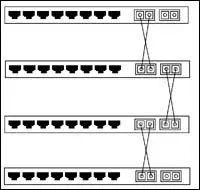
Switches are generally cascaded through common user ports, while some switches provide a dedicated cascade port ( Uplink Port). The difference between these two types of ports is simply that the normal port is MDIX compliant, while the cascade port (or upstream port) is MDI compliant. This results in different wiring methods for the two methods: Crossover Cable when both switches are cascaded through the normal port, and Straight Through Cable when and only when one of them is cascaded through the cascade port.
To facilitate cascading, some switches provide a dual-use port that can be set to MDI or MDIX mode via a switch or management software. Further, all or some of the ports on some switches have MDI/MDIX self-calibration features that automatically differentiate between cable types, making cascading even easier.
When cascading with a switch, you should pay attention to the following issues. In principle, Ethernet switches of any manufacturer and any model can be cascaded with each other, but it does not exclude some special cases where two switches cannot be cascaded. There is a limit to the number of layers that can be cascaded between switches. The most fundamental principle for successful cascading is that the distance between any two nodes should not exceed the maximum span of the media segment. When cascading multiple switches, you should ensure that they all support the Spanning-Tree protocol, both to prevent loops in the network and to allow redundant links to exist.
When cascading, every effort should be made to ensure that the inter-switch trunk links have sufficient bandwidth, for which full-duplex and link aggregation techniques can be used. When full-duplex technology is used for switch ports, not only is the throughput of the corresponding ports doubled, but the relay distance between switches is greatly increased, making it possible to cascade multiple switches that are distributed off-site and far away from each other.
Link aggregation, also called port aggregation, port bundling, and link expansion combination, is defined by IEEE802.3ad standard. It means that two devices are connected in parallel by more than two ports of the same type to transmit data simultaneously in order to provide higher bandwidth, better redundancy, and load balancing. Link aggregation technology provides high-speed connections not only between switches, but also between switches and servers. It is important to note that not all types of switches support both technologies.
Cascading is the most common connection method, i.e., using network cables to connect two switches. There are two types of connections using fiber media connection and twisted pair media connection.
Direct connection of the two switch ports to ensure consistent fiber specifications, port rate, send signal fiber port and receive signal fiber port connected.
Divided into ordinary ports and the use of Uplink port cascade two cases. Ordinary ports connected to each other, the use of cross-twisted pair; a switch using UPlink port connected to the use of straight-through twisted pair. However, it should be noted that some switches have now achieved intelligent judgment, that is, the use of crossover or straight-through line can be used to establish a connection between the two switches.

International transportation + IT O&M outsourcing + self-owned backbone network

Cellular chips + overseas GPS + global acceleration network

Overseas server room nodes + dedicated lines + global acceleration network
Global acceleration network + self-developed patented technology + easy linking

Global Acceleration Network + Global Multi-Node + Cloud Network Integration